
Looking After Your Power Factor
- Sep 21, 2018
- 3 min read
Whether in asset management or the electrical industry, chances are you would have heard of Power Factor Correction and energy efficiency/savings used hand in hand. This certainly isn’t another post with a picture of a beer explaining the difference between KVA & KW (however great beer may be) or explaining why you require Power Factor Correction installed, we want to outline what seems to be the forgotten maintenance routines required to ensure your PFC unit operates to its optimum efficiency.

In many cases the PFC unit is installed, the first energy bill scrutinised and once estimated energy savings are confirmed the PFC unit is forgotten about. If the energy bill rises in the months or years to come, it's put down to the growing energy consumption alone. What is not understood is PFC units are just like cars, requiring regular maintenance to ensure optimum operation. And just like cars when a PFC unit has been operating for a period without sufficient maintenance performed its probably costing you $$$.
The Target
For NSW an installations power factor must be above 0.90 minimum, it’s a regulation by the NSW Service Rules. We recommend that for a PFC unit to be providing sufficient energy savings it should be operating above 0.95 as a minimum and ideally as close to 0.99-1 as possible.
What many people fail to recognise is the difference between 0.98 & 0.92 is not just the number, it's $$$ in your back pocket, and the larger your energy consumption the larger this hit to your back pocket will be.
We like to view this number PF (Power Factor) as two things:
A possible snapshot of the PFC’s current condition.
The PFC’s efficiency in direct relation to the installations characteristics.
So why does the PF deplete over time?
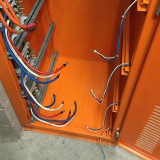
Capacitors

Capacitors are the heart of the PFC unit, the components that improve your Power Factor (PF) and save you $$$. The fact is, all capacitors deplete over time (like car tyres) and require frequent monitoring and replacement when dropping below the manufacturers operating thresholds.
Once one step depletes below this threshold, it's generally a knock-on effect. Usually the controller cycles through each step bringing each in and out over a shared period to ensuring the maximum lifespan is achieved. However, once a step deteriorates the remaining correction (workload) is taken on by the remaining steps, leading to faster depletion over a shorter period.
Controller
Controller settings should consistently be checked and confirmed to ensure the correct values determined by the installation have been input and not changed over time. Such items include target power factor, total number of steps, step auto/manual operation, CT ratio, Faults, Thermostat operation, controller operating voltage.
It may sound straight forward, but the number of PFC units installed with the incorrect CT ratio (effecting current readings) or target power factor programmed incorrectly is alarmingly high, and in some cases the controller requires replacing.
Our Solution
We base our maintenance routines off AS 2467 – Maintenance of electrical switchgear, manufacturer recommendations and years of experience within the industry. Corsence implements a two-staged maintenance routine (6 Monthly - Minor & Annual - Major) that provides a proactive approach to replacement and overhaul ensuring the PFC unit operates efficiently, therefore providing the client with maximum energy savings.
MINOR SERVICE (6 MONTHLY) – TESTING
Visual Inspection of PFC Unit & Surrounding Area
Infrared Scan (using Flir E5 Infrared Camera), results provided in the report
Visual Inspection of Internal Components (Fuses, Contactors, Reactors & Capacitors)
Record Current Load Measurements on each Step to Confirm Capacitor Condition
Check for Capacitor Discharge and/or Visible Signs of Deterioration of Functional Unit(s)
Check Controller Operation (in Manual & Automatic Modes)
Check Fan Operation & Clean Airflow Vents
Report on Completion Including Budget for Repairs
MAJOR SERVICE (ANNUAL) – TESTING & MAINTENANCE
Visual Inspection of PFC Unit & Surrounding Area
Infrared Scan (using Flir E5 Infrared Camera), results provided in the report
Check Controller Operation (in Manual & Automatic Modes)
Check Controller Diagnostics and Settings (CT Ratio, Load Settings)
Confirm PFC Unit is Correcting the Desired Load(s) & Operating as per Design Intent
Record Current Load Measurements on each Step to Confirm Capacitor Condition.
Check for Capacitor Discharge and/or Visible Signs of Deterioration of Functional Unit(s)
Isolation of the PFC Unit from Upstream Protective Device. Tag & Lockout
Visual Inspection of Internal Components (Fuses, Contactors, Reactors & Capacitors)
Internal / External Clean, Wipe, Polish & Vacuum
Confirm Status of All Terminations
Check Step Fuse Condition, Continuity and Operation
Check Control Fuse Integrity & Correct Configuration
Check Fan Operation & Clean Airflow Vents
Confirm Thermostat Operation & Suitability
Insulation Resistance Test & Recording of Results
Visual Check of Labelling Consistency (including warning and safety labels)
PFC Re-energisation, Testing & Commissioning
Report on Completion Including Budget for Repairs


Please feel free to contact us connect@corsence.com if you would like any further information or leave your comment below.


Comments